Marine Propeller Literature and Introduction to All Parts of a Marine Propeller
Introduction
With the growth of human societies and the resulting increased demand for food and resources, as well as job creation and income sources, the utilization of marine opportunities and resources (food, oil, minerals, etc.) has become a priority for all countries, particularly those with access to seas and water bodies. Developing marine industries in any field requires a deeper understanding of the sea, its opportunities, and challenges. This understanding is achieved through precise explorations and studies. In our dear country, Iran, significant marine resources exist at the northern and southern borders, and even in some non-coastal and central regions, offering tremendous potential for food, oil, minerals, tourism, and commercial maritime applications. Iran is, in a sense, a maritime nation, with various food, oil, mineral resources, and unparalleled tourism and recreational opportunities, as well as numerous commercial and navigational applications, creating exceptional opportunities for individuals and companies to utilize and exploit these resources.
It should be noted that utilizing these economic and sometimes strategic resources requires the use of various specialized and general equipment related to the sea and marine industries. One of the key pieces of equipment, used across marine industries from past to present, is various types of waterborne vessels (ships, boats, launches, etc.) with different tonnages developed for diverse applications, ranging from military, policing, reconnaissance, and border patrol to fishing, commercial, tourism, recreational, and other purposes, both manned and unmanned. The equipment installed on these boats and waterborne vessels is often designed to be mechanically simple to reduce costs, simplify maintenance, and enhance reliability, typically consisting of an engine (usually two-stroke), a gearbox (often reduction), and a marine propeller.
Based on the project undertaken, the report of which is presented here, Chapter 1 discusses the literature and specifications of marine propellers. Chapter 2 examines power and rotational speed calculations as key parameters in evaluating marine propulsion systems. Finally, Chapter 3 addresses the transmission of power (torque) from the shaft and gearbox to the propeller using a mechanism called a spline.
Chapter 1: Marine Propeller Literature and Analysis of Yamaha-85 Propeller
Marine propellers, as water-displacing and propulsive components, are used in all waterborne and transport vessels, including boats, ships, submarines, and more. Various classifications have been proposed based on their shape, efficiency, and application, with variations in blade count depending on the engine and gearbox rotation direction. First, a general introduction to the marine propeller and the shape and specifications of its various parts is necessary:
Figure 1.1: Introduction to All Parts of a Marine Propeller
Leading Edge: The first part of the blade to contact water, thicker for strength to cut through water with high speed and force.
Trailing Edge: The last part where water leaves the blade, thinner to minimize pressure loss and wake fluctuations.
Inner Hub: The connection point of the propeller to the rubber bush and spline, with thicker and stronger blade roots.
Outer Hub: The surface connecting blades and their roots to the propeller, in contact with water.
Blade Root: The connection point of the blade to the outer hub, designed for strength.
Ribs: These connect the inner and outer hubs, reducing propeller weight while maintaining strength. In some propellers, the space between ribs serves as a passage for hot exhaust gases and chemicals from the engine, reducing weight without compromising strength.
Pressure Face: During rotation, due to the propeller’s geometry, water speed decreases on this surface, increasing static pressure, hence called the pressure face.
Diffuser Ring: Reduces pressure behind the propeller, preventing hot gas backflow.
Blade Count: The number of blades installed on a marine propeller varies and is a key factor affecting performance. Extensive research has been conducted, and articles have been published on blade count and type. The Yamaha-85 propeller, studied in this project, has 3 blades.
Blade Profile: Observing the blade shape reveals a specific profile similar to aircraft wing and helicopter rotor airfoils, due to their similar function of generating thrust (in vessels) or lift (in aircraft and helicopters) by creating a pressure difference across a surface in a fluid (air or water). Blades must have an airfoil-like shape with a curved and twisted cross-section, as this increases efficiency compared to flat blades. A flat blade lacks the efficiency of a curved, contoured, and twisted blade.
Rake Angle: The angle between the blade and a line perpendicular to the blade axis, as shown in Figure 1.2. It can be zero, constant (Flat Rake), or variable (Progressive Rake). Blades with a higher rake angle typically provide greater speed and thrust. Propellers with better performance usually have a rake angle between 20 and 30 degrees. The Yamaha-85 propeller has a rake angle of approximately 15 degrees.

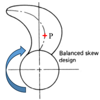
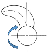
Skew Angle: The angle between the line passing through the centers of all blade sections and the tangent to the blade root. The skew angle can be generated as follows:
No Skew: If the line passing through the centers of all sections moves straight from the starting point (blade root) to the endpoint (blade tip) without any curvature or change in direction, it is called a No Skew propeller (Figure 1.3).
Balanced Skew: If the line passing through the centers of all sections changes direction from the blade root to the tip, initially curving toward the rotation direction and then against it, it is called a Balanced Skew propeller (Figure 1.4).
Biased Skew: If the line passing through the centers of all sections moves without changing direction, curving against the rotation direction from root to tip, it is called a Biased Skew propeller (Figure 1.5).
Typically, if the skew angle exceeds 25 degrees, the propeller is called a High Skew Propeller. The following classification addresses different skew angles and their effects on propeller shape:

High-skew propellers are designed to eliminate cavitation-induced pressure pulses, reducing vibrations by up to 30% compared to no-skew propellers. Skew angle does not affect efficiency but reduces vibrations, making it crucial for military submarines and other vessels requiring minimal noise during missions.

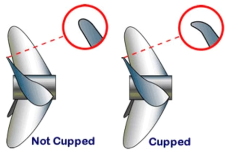
Cupped Propeller: As shown in Figure 1.6, this feature involves a curvature at the blade tip, resembling a cup, hence called “cupped.” Cupped propellers improve control during acceleration and turning due to better water adhesion to the propeller, and they increase the upper speed limit. Overall, cupping enhances propeller efficiency and performance. The Yamaha-85 propeller studied in this project is a non-cupped propeller.
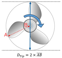
Rotation Direction: The propeller can rotate clockwise (right-hand) or counterclockwise (left-hand), determined by viewing the propeller from the face (Figure 1.7). The Yamaha-85 propeller is right-hand.

In vessels with two propellers, the right propeller typically rotates clockwise, and the left counterclockwise, to balance torques. Some vessels allow reverse motion through reverse propeller rotation (with the condition of generating reverse thrust), but this is not covered here.


